Step by step instructions for how to install your 114-3505 LED Light Kit
Installing the LED Light Kit
CLICK HERE TO BUY YOUR LED LIGHT KIT
Note: For installation assistance, contact an Authorized Service Dealer.
Light Kit GrandStand Model No. 114-3505 Installation
Loose Parts, use the chart below to verify that all parts have been shipped
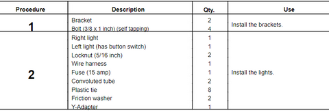
1. Installing the Brackets
Parts needed for this procedure:
2 Bracket
4 Bolt (3/8 x 1 inch) (self tapping)
Procedure:
1. Stop the engine, set the parking brake, and remove the
key from the ignition switch (Figure 1).
2. Remove the negative (-) battery cable from the battery.
3. Install the 2 brackets to the side of the machine with 4
bolts (3/8 x 1 inch).
Note: These are thread-forming (self-tapping) bolts and the frame holes do not require tapping.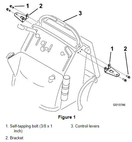 2. Installing the Lights
Parts needed for this procedure:
1 Right light
1 Left light (has button switch)
2 Locknut (5/16 inch)
1 Wire harness
1 Fuse (15 amp)
2 Convoluted tube
8 Plastic tie
2 Friction washer
1 Y-Adapter
Procedure:
1. Install the convoluted tube onto the exposed wires
connected to the lights.
Note: Use 4 plastic ties on each end of the convoluted
tube to secure it to the wires (Figure 3).
2. Slide the light connectors into the holes in the brackets
(Figure 2).
Note: The lock washer fits inside the friction washer and centers the friction washer.
Important: Do not overtighten the hardware for the lights. Gently tighten the nut to secure the light and test the friction to move light. Loosen or tighten the nut to control the friction holding the light and allowing the light to be aimed.
3. Discard the 2 nuts included with the lights.
4. Install the left-hand light (with the button switch) to
the left bracket with a locknut (5/16 inch), a friction
washer, and a lock washer and bolt include with the
light (Figure 3).
Note: Ensure the light is in place so the friction allows
the light to pivot and swivel.
5. Install the right light to the right bracket with a locknut
(5/16 inch), a friction washer, and a lock washer and
bolt included with the light (Figure 3).
Note: Ensure the light is in place so the friction allows the light to pivot and swivel.
6. Remove the hairpin cotter securing the rear cushion
bracket (Figure 4).
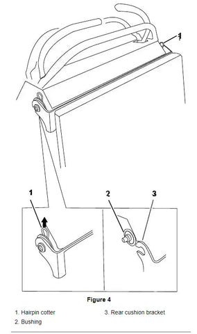
7. Slide the bushing next to the machine (Figure 4).
8. Lower the rear cushion bracket onto the platform
(Figure 4).
9. Route the light kit wire harness in front of the control
cables and near the traction unit wire harness.
10. Plug the wire harness into the lights (Figure 5).
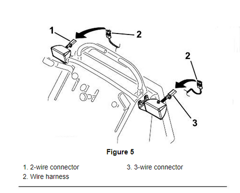
Note: The right light has a 2-wire connector and
the left light (with the button switch) has a 3-wire
connector.
11. Route the wire harness down to the fuse block.
12. Locate the short connector behind the fuse block and
remove the insulator cap from the connector.
13. Install the Y-adapter. Plug the single end of the Y-adapter into the short connector behind the fuse block (Figure 6). Plug the wire harness for the lights into the other end of the Y-adapter (Figure 6). Plug the wire harness for the Hydraulic Cooling Assembly (if present) into the Y-adapter (Figure 6).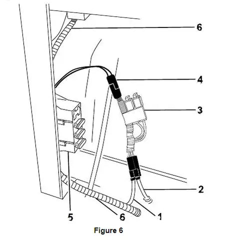

14. Install the fuse (Figure 7). 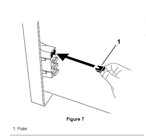

15. Secure the Y-adapter to the main wire harness with a
wire tie supplied in the kit.
Note: Position the Y-adapter so that the fuses are in
an upright position (Figure 6).
16. Secure the light kit wire harness to the traction unit
with 3 plastic ties supplied in the kit.
17. Install the rear cushion (Figure 4).
18. Install the negative (-) battery cable to the battery.
Operation
Operating the Lights
Note: The lights can only be on when the ignition switch
is in the Run position.
1. With the ignition switch in the Run position, turn the
lights on or off by depressing the button switch on the
left light.
2. Pivot or swivel the lights to the desired position.
